Connecting to the CODESYS V3 PLC Simulator
This document demonstrates how to use the CODESYS V3 TCP plugin to connect to the CODESYS V3 PLC simulator for reading and writing data.
Installation of the CODESYS V3 Development Environment
The installation package for the CODESYS V3 development environment can be downloaded from the official CODESYS website. The version used in this example is CODESYS V3.5 SP12. There may be slight differences between versions, but the overall process is similar.
Creating a New Project
- Click File -> New Project, select Standard project and name it test.
- Select CODESYS Control Win v3 x64 for the device and Structured Text (ST) for PLC_PRG.
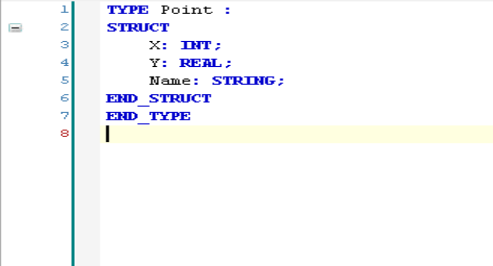
- Right-click Application and add an object DUT, then create a new structure Point with the following definition.
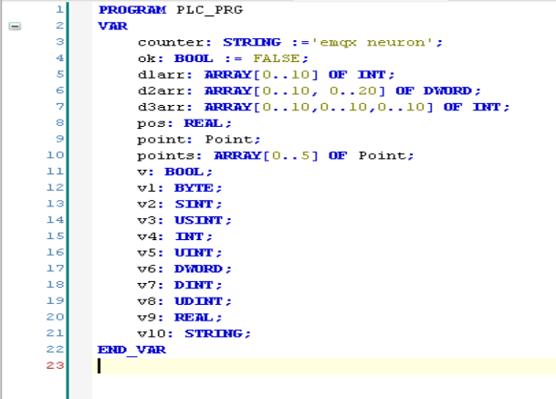
- Open PLC_PRG and define variables as shown below.
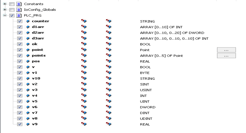
- Right-click Application, add an object Symbol Configuration, click Build, and select variables to export as shown below.
- Click Build, then Build -> Generate Code. The symbol file
test.Device.Application.xmlwill be generated in the project directory with the following content.
xml
<?xml version="1.0" encoding="utf-8"?>
<Symbolconfiguration xmlns="http://www.3s-software.com/schemas/Symbolconfiguration.xsd">
  <Header>
    <Version>3.5.11.0</Version>
    <SymbolConfigObject version="3.5.12.0" runtimeid="3.5.12.0" libversion="3.5.11.0" compiler="3.5.12.0" lmm="3.5.12.0" profile="CODESYS V3.5 SP12+" settings="SupportOPCUA, XmlIncludeComments, LayoutCalculator=OptimizedClientSideLayoutCalculator" />
    <ProjectInfo name="test" devicename="Device" appname="Application" />
  </Header>
  <TypeList>
    <TypeSimple name="T_BOOL" size="1" swapsize="0" typeclass="Bool" iecname="BOOL" />
    <TypeSimple name="T_BYTE" size="1" swapsize="1" typeclass="Byte" iecname="BYTE" />
    <TypeSimple name="T_DINT" size="4" swapsize="4" typeclass="DInt" iecname="DINT" />
    <TypeSimple name="T_DWORD" size="4" swapsize="4" typeclass="DWord" iecname="DWORD" />
    <TypeSimple name="T_INT" size="2" swapsize="2" typeclass="Int" iecname="INT" />
    <TypeSimple name="T_REAL" size="4" swapsize="4" typeclass="Real" iecname="REAL" />
    <TypeSimple name="T_SINT" size="1" swapsize="1" typeclass="SInt" iecname="SINT" />
    <TypeSimple name="T_STRING" size="81" swapsize="0" typeclass="String" iecname="STRING" />
    <TypeSimple name="T_UDINT" size="4" swapsize="4" typeclass="UDInt" iecname="UDINT" />
    <TypeSimple name="T_UINT" size="2" swapsize="2" typeclass="UInt" iecname="UINT" />
    <TypeSimple name="T_USINT" size="1" swapsize="1" typeclass="USInt" iecname="USINT" />
    <TypeArray name="T_ARRAY__0__10__0__10__0__10__OF_INT" size="2662" nativesize="2662" typeclass="Array" iecname="ARRAY [0..10, 0..10, 0..10] OF INT" basetype="T_INT">
      <ArrayDim minrange="0" maxrange="10" />
      <ArrayDim minrange="0" maxrange="10" />
      <ArrayDim minrange="0" maxrange="10" />
    </TypeArray>
    <TypeArray name="T_ARRAY__0__10__0__20__OF_DWORD" size="924" nativesize="924" typeclass="Array" iecname="ARRAY [0..10, 0..20] OF DWORD" basetype="T_DWORD">
      <ArrayDim minrange="0" maxrange="10" />
      <ArrayDim minrange="0" maxrange="20" />
    </TypeArray>
    <TypeArray name="T_ARRAY__0__10__OF_INT" size="22" nativesize="22" typeclass="Array" iecname="ARRAY [0..10] OF INT" basetype="T_INT">
      <ArrayDim minrange="0" maxrange="10" />
    </TypeArray>
    <TypeUserDef name="T_Point" size="89" nativesize="92" typeclass="Userdef" pouclass="STRUCTURE" iecname="Point">
      <UserDefElement iecname="X" type="T_INT" byteoffset="0" vartype="VAR" />
      <UserDefElement iecname="Y" type="T_REAL" byteoffset="4" vartype="VAR" />
      <UserDefElement iecname="Name" type="T_STRING" byteoffset="8" vartype="VAR" />
    </TypeUserDef>
    <TypeArray name="T_ARRAY__0__5__OF_Point" size="552" nativesize="552" typeclass="Array" iecname="ARRAY [0..5] OF Point" basetype="T_Point">
      <ArrayDim minrange="0" maxrange="5" />
    </TypeArray>
  </TypeList>
  <NodeList>
    <Node name="Application">
      <Node name="PLC_PRG">
        <Node name="counter" type="T_STRING" access="ReadWrite" />
        <Node name="d1arr" type="T_ARRAY__0__10__OF_INT" access="ReadWrite" />
        <Node name="d2arr" type="T_ARRAY__0__10__0__20__OF_DWORD" access="ReadWrite" />
        <Node name="d3arr" type="T_ARRAY__0__10__0__10__0__10__OF_INT" access="ReadWrite" />
        <Node name="ok" type="T_BOOL" access="ReadWrite" />
        <Node name="point" type="T_Point" access="ReadWrite" />
        <Node name="points" type="T_ARRAY__0__5__OF_Point" access="ReadWrite" />
        <Node name="pos" type="T_REAL" access="ReadWrite" />
        <Node name="v" type="T_BOOL" access="ReadWrite" />
        <Node name="v1" type="T_BYTE" access="ReadWrite" />
        <Node name="v10" type="T_STRING" access="ReadWrite" />
        <Node name="v2" type="T_SINT" access="ReadWrite" />
        <Node name="v3" type="T_USINT" access="ReadWrite" />
        <Node name="v4" type="T_INT" access="ReadWrite" />
        <Node name="v5" type="T_UINT" access="ReadWrite" />
        <Node name="v6" type="T_DWORD" access="ReadWrite" />
        <Node name="v7" type="T_DINT" access="ReadWrite" />
        <Node name="v8" type="T_UDINT" access="ReadWrite" />
        <Node name="v9" type="T_REAL" access="ReadWrite" />
      </Node>
    </Node>
  </NodeList>
</Symbolconfiguration>
Start the Simulator and Download the Program
- Run
CODESYS Control Win v3 x64directly from the Windows menu bar. - Switch the development environment to the Device configuration page, press
Enterto connect to the simulator. The first connection will prompt for username and password. - Log in to the simulator with the configured username and password, download the program, and run it.
Configure Neuron Node to Connect to CODESYS V3 Simulator
- In the Southb Devices, click Add Device and select the CODESYS V3 TCP plugin to create a node for connecting to the CODESYS V3 simulator.
- After creating the node, click Device Configuration to enter the configuration page and configure the node information based on the actual situation.
- Device IP Address: The IP address of the device, which is the IP address of the host running the simulator.
- Device Port: The port of the device, default is 11740.
- Connection Timeout: Default is 3000.
- Username: The configured username.
- Password: The configured password.
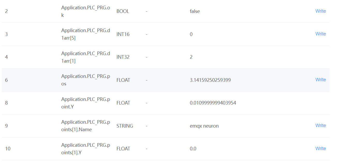
- Create groups and points in the created southbound device node, and concatenate the point addresses according to the NodeList in the exported XML file.
- Go to the Neuron Data Monitoring, select the corresponding device and group, and view the collected data points as shown below.